How a Switch Mode Power Supply (SMPS) Powers Electronic Devices
2026-05-11
54
Catalog
Figure 1. Switch Mode Power Supply (SMPS) Internal Blocks
What Is a Switch Mode Power Supply (SMPS)?
A Switch Mode Power Supply, or SMPS, is a type of power supply that converts electrical power from one voltage to another in an efficient way. Its main purpose is to give electronic devices the correct power they need to operate properly.
SMPS is widely used in modern electronics since it wastes less energy and produces less heat compared to older power supply designs. This helps devices run more efficiently while also allowing products to be smaller and lighter. As a result, SMPS has become a better choice in many electronic systems today.
When we say efficient power conversion, it means the SMPS can transfer more electrical energy to the device instead of losing a large amount of it as heat. This improves performance and helps save power, especially in devices that are used for many hours.
You can find SMPS in many everyday products such as computers, laptops, phone chargers, televisions, LED lights, gaming consoles, industrial equipment, and communication devices. Its ability to provide stable power efficiently is one of the main reasons why it is so required in modern electronics.
SMPS vs Linear Power Supply: What’s the Difference?
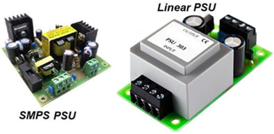
Figure 2. SMPS PSU vs Linear PSU
SMPS and linear power supplies both give stable power to electronic devices, but they are best for different situations. The main difference is that SMPS is more efficient and compact, while a linear power supply is simpler and produces cleaner output power.
|
Parameter |
SMPS |
Linear
Power Supply |
|
Efficiency |
Usually around 80% to
95% efficient |
Usually around 40% to
60% efficient |
|
Heat Generation |
Produces less heat
because less energy is wasted |
Produces more heat
because extra energy becomes heat |
|
Transformer Size |
Uses a small
high-frequency transformer |
Uses a large
low-frequency transformer |
|
Weight |
Lightweight and
compact |
Heavier and bulkier |
|
Operating Frequency |
Often works from 20
kHz to several hundred kHz |
Normally works at 50
Hz or 60 Hz |
|
Electrical Noise and
EMI |
Generates more
switching noise and EMI |
Produces cleaner and
quieter output |
|
Cooling Requirement |
Smaller heat sinks
are often enough |
Larger heat sinks may
be needed |
|
Circuit Complexity |
More complex circuit
design |
Simpler circuit
design |
|
Power Density |
Higher power output
in a smaller size |
Lower power density |
|
Cost |
Lower cost in mass
production |
Can become expensive
in higher power designs |
|
Reliability |
Good for modern
compact electronics |
Good for simple and
low-noise systems |
|
Common Applications |
Computers, chargers,
TVs, industrial systems, LED drivers |
Audio amplifiers, lab
equipment, radio systems |
Inside a Switch Mode Power Supply (SMPS)
Inside an SMPS, electrical power passes through several main sections before it becomes stable DC power for a device. Each section has a specific job, and all of them work together to convert and control the power safely and efficiently.
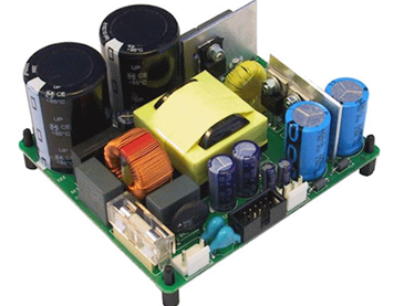
Figure 3. Open-Frame SMPS Circuit Board
The basic power flow inside an SMPS is:
AC Input → EMI Filter → Rectifier → Filter Capacitor → Switching Circuit → Transformer → Output Rectifier → Output Filter → DC Output
The process starts with the AC input from the wall outlet. The power first goes through an EMI filter, which helps reduce electrical noise and interference.
Next, the power enters the rectifier, where the AC voltage is changed into DC voltage. After that, a filter capacitor smooths the voltage before it moves to the switching stage.
The switching circuit controls the power at very high speed to improve efficiency. The power then passes through a transformer, which adjusts the voltage level and helps isolate the input and output sides.
Finally, the power goes through the output rectifier and output filter to create a clean and stable DC output for the electronic device.
EMI/EMC Filter and Noise Suppression
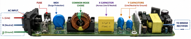
Figure 4. EMI/EMC Filter Components in an SMPS
An SMPS operates using high-speed switching, and this switching action can create unwanted electrical noise called EMI (Electromagnetic Interference). If this noise is not controlled, it can affect nearby electronic devices, communication systems, audio equipment, and even the normal operation of the power supply itself. This is why EMI filtering is a main part of almost every modern SMPS design.
The EMI/EMC filter is usually placed near the AC input section of the power supply. Its job is to reduce electrical noise entering or leaving the SMPS. Without proper filtering, switching noise can travel through power lines or radiate into the air, causing interference with other electronics.
There are two main types of noise in an SMPS:
• Conducted noise – electrical noise that travels through wires and power cables
• Radiated noise – noise that spreads through the air like electromagnetic waves
Both types can create problems in sensitive electronic systems. For example, EMI can cause unstable signals, communication errors, audio noise, display flickering, or unexpected behavior in nearby devices.
To reduce this interference, SMPS circuits use several EMI filter components, including: Common mode chokes, X and Y capacitors, and Ferrite beads or inductors. These components work together to keep the power supply cleaner and safer for other electronics.
Bridge Rectifier and AC-to-DC Conversion
In an SMPS, the AC input from the wall outlet must be converted into DC before it reaches the switching stage. This first conversion step is called rectification. A bridge rectifier is usually used for this process. It uses four diodes arranged in a bridge circuit. These diodes guide the current so the negative half of the AC waveform is flipped into the positive direction.
This process is called full-wave rectification since both the positive and negative halves of the AC waveform are used.
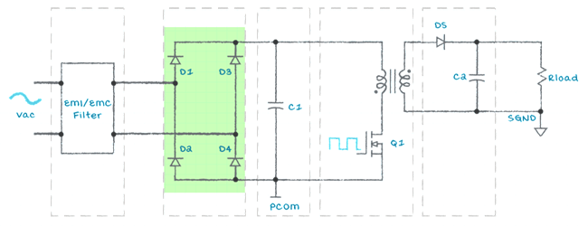
Figure 5. Bridge Rectifier in an SMPS
|
Signal
Type |
Waveform
Behavior |
|
AC Input Waveform |
Alternates between
positive and negative voltage |
|
Rectified Output
Waveform |
Pulsating DC with
only positive pulses |
Input Bulk Capacitor and DC Bus Voltage
After the AC input is converted into pulsating DC by the bridge rectifier, the voltage is still not smooth enough for the SMPS. To improve this, the power passes through an input bulk capacitor.
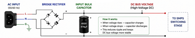
Figure 6. Input Bulk Capacitor and DC Bus Formation
The bulk capacitor stores electrical energy and helps smooth the DC voltage. When the rectified voltage rises, the capacitor charges and stores energy. When the voltage drops, the capacitor releases stored energy. This charging and discharging process helps keep the DC voltage more stable.
Without the bulk capacitor, the DC voltage would continuously rise and fall, creating large ripple on the DC bus. The capacitor helps reduce this ripple and forms a smoother high-voltage DC supply for the next stages of the SMPS.
In many SMPS designs, the rectified AC input becomes a high-voltage DC bus after smoothing.
|
AC
Input Voltage |
Approximate
DC Bus Voltage |
|
120V AC |
Around 170V DC |
|
230V AC |
Around 325V DC |
Power Switching Stage and PWM Operation
The power switching stage controls the high-voltage DC inside the SMPS. It usually uses a MOSFET or power transistor that rapidly turns ON and OFF like a fast electronic switch.
This switching is controlled by PWM, or Pulse Width Modulation. PWM changes how long the switch stays ON during each cycle. This ON time is called the duty cycle.
|
PWM
Condition |
Meaning |
|
Short ON time |
Less power is
delivered |
|
Long ON time |
More power is
delivered |
|
Fast ON/OFF
switching |
Better
control and efficiency |
The switching happens at high frequency, usually thousands of times per second. This allows the SMPS to control power more accurately while keeping the design compact.
Switching improves efficiency as the MOSFET is mostly either fully ON or fully OFF. This reduces wasted energy as heat, which is why an SMPS is usually smaller, cooler, and more efficient than a linear power supply.
Isolation Transformer and Magnetic Power Transfer
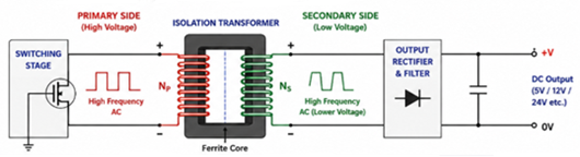
Figure 7. Isolation Transformer in an SMPS
The isolation transformer in an SMPS transfers power from the input side to the output side using magnetic energy. It does this without a direct electrical connection between the two sides, which helps improve safety.
One main purpose of the transformer is electrical isolation. This separates the high-voltage input side from the low-voltage output side, helping protect you and the connected device from dangerous mains voltage.
The transformer also changes the voltage level. Depending on the design, it can step the voltage down for low-voltage outputs like 5V, 12V, or 24V, or step it up for applications that need higher voltage.
SMPS transformers usually use a ferrite core as ferrite works well at high switching frequencies. Since the SMPS operates at high frequency, the transformer does not need to be large like a traditional 50Hz or 60Hz transformer.
Power is transferred magnetically: the switching current creates a changing magnetic field in the transformer core, and this magnetic field transfers energy to the secondary winding. This is why SMPS transformers are compact, lightweight, and efficient while still providing isolation and voltage conversion.
Output Rectifier and Secondary-Side Conversion
After power passes through the transformer, the output is still in the form of high-frequency AC. Before it can power electronic devices, it must be converted back into DC. This process is called secondary-side rectification.
The output rectifier does this conversion using special fast diodes. These diodes allow current to flow in the correct direction so the output becomes DC.
For this reason, many SMPS designs use Schottky diodes or fast-recovery diodes. Schottky diodes are popular as they have lower voltage drop and faster switching speed, which helps reduce power loss and heat generation. Fast-recovery diodes are also designed to switch quickly at high frequencies.
Some modern SMPS designs use synchronous rectification instead of standard diodes. In this method, MOSFETs are used for rectification to further improve efficiency, especially in low-voltage and high-current power supplies.
Fast-switching rectifiers are required as the transformer output changes very quickly at high frequency. If slow diodes are used, switching losses increase, efficiency drops, and more heat is generated. This is why high-speed rectification components are used in modern SMPS designs.
Output Filter and Ripple Reduction
After the output rectifier converts the transformer output into DC, the voltage is still not perfectly smooth. It may still contain ripple, which means small unwanted voltage changes remain in the output.
The output filter helps smooth this DC voltage before it reaches the device. It usually uses capacitors and sometimes inductors to reduce ripple and noise. The capacitor stores and releases energy to keep the output voltage more stable, while the inductor helps resist sudden current changes.
Ripple reduction is required as many electronic circuits need clean and stable DC power. Too much ripple can cause unstable operation, noise, overheating, or poor performance in sensitive devices.
Voltage, Current, and Temperature Protection in SMPS
An SMPS uses several protection circuits to keep the power supply and connected devices safe during abnormal conditions. These protection features help improve stability, reliability, and overall safety.
One main function is voltage feedback control. The SMPS continuously monitors the output voltage through a feedback loop. If the output voltage becomes too high or too low, the control circuit adjusts the operation of the power supply to keep the output stable.
Overvoltage protection (OVP) protects the load when the output voltage rises above a safe level. If excessive voltage is detected, the SMPS may reduce the output, shut down temporarily, or stop operating to prevent damage to electronic components.
Overcurrent protection (OCP) monitors the output current. If too much current flows as of overload or short circuit conditions, the protection circuit limits or shuts down the output to protect the power supply and connected devices.
SMPS units also use thermal shutdown protection. If the internal temperature becomes too high due to overload, poor cooling, or component failure, the power supply automatically reduces operation or shuts down to prevent overheating damage.
aðgerðarpróf.Helstu hagkvæmar vörur og besta þjónustan er eilíf skuldbinding okkar.
Heitt grein
- LM358 Tvískiptur rekstrar magnari Alhliða leiðarvísir: Pinouts, hringrásarmyndir, jafngildi, gagnleg dæmi
- Eru CR2032 og CR2016 skiptanleg?
- Að skilja muninn ESP32 og ESP32-S3 tæknilega og frammistöðu greiningu
- Að velja rétta rafhlöðu: Leiðbeiningar um AG4, LR626, LR66, 177/376/377, SR626 og SR626SW jafngildi
- BC547 Transistor Basics: Pinout, umsóknarrásir, aðrar/viðbótargerðir
- NPN vs. PNP: Hver er munurinn?
- ESP32 vs STM32: Hvaða örstýring er betri fyrir þig?
- Hvað er MOSFET og hvernig það virkar?
- Rafmagns gengi grunn: Vinnuaðgerð, gerðir og notkun
- PNP smárar: Uppbygging, vinnandi meginregla og notkun
 Aluminum Polymer Capacitors Explained: How They Work and Why They Matter
2026-05-11
 Op-Amp Slew Rate Guide: Formúla, Mæling, Áhrif og Val
2026-05-09
Algengar spurningar [FAQ]
1. Why is an SMPS more efficient than a linear power supply?
An SMPS is more efficient because it uses high-speed switching instead of continuously wasting excess energy as heat. The power transistor mostly stays fully ON or fully OFF, which reduces power loss and improves energy efficiency.
2. Why does an SMPS need an EMI filter?
An EMI filter reduces electrical noise created by high-frequency switching inside the SMPS. Without proper filtering, this noise can interfere with nearby electronics, communication systems, audio devices, and sensitive circuits.
3. What happens if the bridge rectifier fails in an SMPS?
If the bridge rectifier fails, the AC input cannot be properly converted into DC. This may cause the power supply to stop working, blow the fuse, produce unstable voltage, or damage other components inside the SMPS.
4. Why does an SMPS use high-frequency switching?
High-frequency switching improves efficiency and allows the transformer and other components to become smaller and lighter. This helps make modern power supplies more compact and energy efficient.
5. How does the output filter reduce ripple in an SMPS?
The output filter uses capacitors and inductors to smooth the DC voltage. Capacitors store and release energy, while inductors help resist sudden current changes, reducing ripple and electrical noise.
6. What happens if an SMPS overheats?
If the temperature becomes too high, the thermal protection circuit may reduce operation or shut down the power supply completely. This helps prevent damage to internal components and improves long-term reliability.
7. Can an SMPS work with both 120V AC and 230V AC input?
Many modern SMPS designs support a wide input range, allowing them to operate from both 120V AC and 230V AC supplies. This is common in laptop chargers, phone adapters, and industrial power supplies.
Heitt hlutanúmer
 18125C225KAT2A
 UMK107BJ105KA-T
 CL10C160JB8NNNC
 CGA5L1X7R1V475M160AC
 CGA3E1X7S1C155M080AC
 C2012JB2A332M085AA
 C1005X6S1A334M050BC
 LD052C331KAB2A
 1206PC563KAT1A
 12067C471JAT2A
- 1812HA331KATME
- T494C106M020AT
- PGB0010603NR
- AO4576
- SPL505YC256BTT
- LFE2M20SE-7FN256C
- MKE02Z16VLD2
- ATMEGA164P-A15AZ
- QS3257S1G
- MAX8971EWP+T
- 2FI100F-060N
- FZ1200R17KF6-B2
- V300C48C150A
- MAX3243CDBG4
- TH58NVG3S0HBAI4
- TS3A5018DGVR
- CM1453-08CP
- BC547
- FAN21SV06MPX
- PCI9054-AB50PI
- CY7C3711-110JC
- HA12134AF-EL
- LGE101B-LF-SA
- LTC1747CFW
- M29F102BB-70K1
- M36L0R705
- MAX705EUA
- MB91382BGL-GE1
- PCD3311T/0
- RJK0383DPA-00-J53
- FXO60AF8-03-A3-LB1-L
- LEXVELDH17AMG
- MTS142LG-BO
- RC5039M-T
- STM6822TWY6
- TEN20-2413
- OCA7890BAD
- D43256BGU70LL
- PESD3V3L1BA.115